
Demonstration Relay
Product Specification Sheet
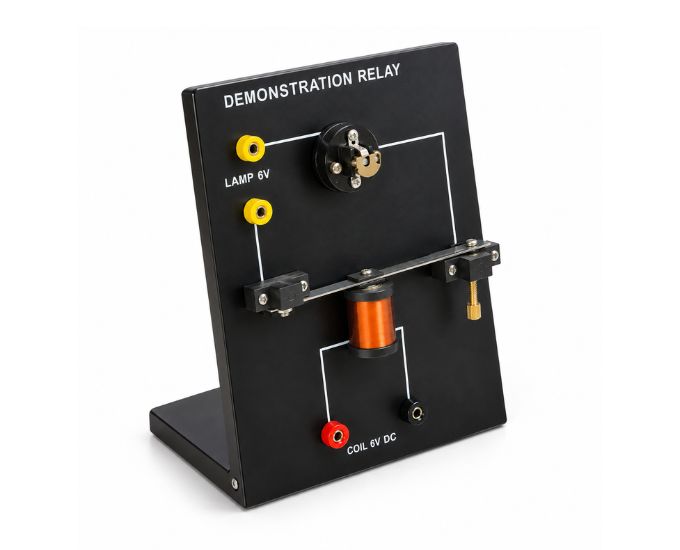
Demonstration Relay
Model Number: MTME-41
The Demonstration Relay is designed to investigate the operation of an electromagnetic relay and demonstrate its practical use in automatic switching circuits. Micro Technologies supplies the apparatus with two electrically separate circuits, allowing the relay-control circuit to operate independently from the lamp circuit. When current flows through the relay coil, the resulting electromagnetic field attracts an iron armature, closes the contact, and illuminates the lamp. Switching off the coil current releases the contact and opens the lamp circuit.
Product Specification
The Demonstration Relay is designed to investigate the operation of an electromagnetic relay and demonstrate its practical use in automatic switching circuits. Micro Technologies supplies the apparatus with two electrically separate circuits, allowing the relay-control circuit to operate independently from the lamp circuit. When current flows through the relay coil, the resulting electromagnetic field attracts an iron armature, closes the contact, and illuminates the lamp. Switching off the coil current releases the contact and opens the lamp circuit.
Product Description
The Demonstration Relay is a practical apparatus designed to provide a clear visual investigation of how an electromagnetic relay operates and how it can be used to control a separate electrical circuit.
A relay allows one electrical circuit to control the switching of another circuit without requiring the two circuits to be electrically connected. This makes the apparatus particularly useful for investigating the principles of electromagnetic switching, circuit isolation, and automatic control.
The Demonstration Relay incorporates two separate circuits. One circuit energizes the relay coil, while the second circuit contains the lamp and switching contacts.
When a suitable low-voltage current is supplied to the relay coil, an electromagnetic field is generated around the coil. This magnetic field attracts the iron armature toward the electromagnet.
Movement of the armature operates the relay contact. The contact then completes the separate lamp circuit, allowing current to flow through the lamp and causing it to illuminate.
When current to the relay coil is switched off, the electromagnetic field collapses. The armature returns to its original position, the contact opens, and the lamp circuit is interrupted.
Micro Technologies provides the apparatus as a clear demonstration of how a relatively small control current can operate another electrical circuit through electromagnetic action.
The open and visible arrangement makes the movement of the armature and switching contact easy to observe, helping users connect the electrical input at the coil with the mechanical movement and resulting switching action.
The Demonstration Relay can therefore be used for experiments involving electromagnetism, relays, electrical switching, circuit isolation, automatic control, and electromagnetic actuators.
Features
- Electromagnetic relay demonstration apparatus
- Two electrically separate circuits
- Electromagnetic relay coil
- Iron armature arrangement
- Visible switching contact
- Separate lamp circuit
- Demonstrates automatic switching
- Demonstrates electromagnetic attraction
- Shows relay ON and OFF operation
- Low-voltage experimental configuration
- Clear visual operating arrangement
- Suitable for repeated circuit experiments
- Compact bench-top construction
- Reusable apparatus
Benefits
- Clearly demonstrates how an electromagnetic relay operates
- Shows how one circuit can control another separate circuit
- Visible armature movement improves understanding of relay action
- Lamp provides immediate indication of switching operation
- Demonstrates electrical-to-mechanical-to-electrical control
- Useful for introducing automatic control principles
- Separate circuits demonstrate electrical isolation
- Simple configuration minimizes experimental setup
Product Specifications
| Specification | Details |
|---|---|
| Product Name | Demonstration Relay |
| Internal Model No. | MT-41165 |
| Product Type | Electromagnetic Relay Demonstrator |
| Number of Circuits | 2 Separate Circuits |
| Control Element | Electromagnetic Coil |
| Moving Element | Iron Armature |
| Switching Element | Relay Contact |
| Output Indicator | Lamp |
| Circuit Operation | Electromagnetic Switching |
| Supply Type | Suitable Low-Voltage Supply |
| Primary Principle | Electromagnetic Relay Operation |
| Primary Application | Automatic Switching & Relay Experiments |
Applications
- Electromagnetic relay experiments
- Relay switching demonstrations
- Automatic switching experiments
- Electromagnetic attraction investigations
- Separate control and load circuit experiments
- Electrical control circuit demonstrations
- Electromagnetic actuator experiments
- Basic automation investigations
- Electricity and electromagnetism experiments
Available Variants
- MT-41165 – Standard Demonstration Relay
- Electromagnetic Relay Demonstrator
- Relay Switching Experiment Apparatus
- Automatic Lamp Control Relay Apparatus
- Customized configurations for bulk requirements
FAQs
What is a Demonstration Relay used for?
It is used to demonstrate how an electromagnetic relay operates and how one electrical circuit can automatically switch another separate circuit.
How many circuits are used in the apparatus?
The apparatus uses two electrically separate circuits—one for operating the relay coil and another for the lamp.
How does the relay operate?
When current flows through the relay coil, it produces a magnetic field that attracts an iron armature. This movement operates the switching contact.
What happens when the relay coil is energized?
The electromagnetic field attracts the armature, causing the contact to close and complete the lamp circuit.
What happens to the lamp when the contact closes?
The lamp circuit is completed, allowing current to flow and the lamp to illuminate.
What happens when the relay coil is switched off?
The magnetic field collapses, the armature returns, the contact opens, and the lamp circuit is switched off.
Are the relay and lamp circuits electrically connected?
No. The apparatus demonstrates how the two circuits can remain electrically separate while the relay mechanically controls the switching contact.
What is the purpose of the iron armature?
The iron armature is attracted by the energized electromagnet and mechanically operates the relay contact.
Does the apparatus demonstrate electromagnetic attraction?
Yes. Attraction of the iron armature toward the energized coil is a central part of the demonstration.
Can it demonstrate automatic switching?
Yes. The relay automatically switches the separate lamp circuit according to whether the relay coil is energized or de-energized.
What type of electrical supply is required?
A suitable low-voltage electrical supply should be used according to the apparatus specifications.
Can Demonstration Relay apparatus be supplied in bulk?
Yes. Micro Technologies can supply Demonstration Relay apparatus in bulk for laboratories, universities, colleges, research facilities, scientific equipment distributors, and institutional procurement.
Why Choose Our Products
- Clear electromagnetic relay operation
- Two separate circuit arrangement
- Visible iron armature and switching action
- Lamp indication of relay operation
- Demonstrates circuit isolation and control
- Compact and reusable construction
- Suitable for repeated experiments
- Bulk supply available
Call to Action
Demonstrate electromagnetic switching and automatic circuit control with the Demonstration Relay from Micro Technologies. Contact us for competitive quotations, bulk orders, distributor requirements, institutional procurement, and complete electricity and electromagnetism laboratory equipment solutions.