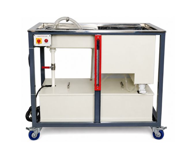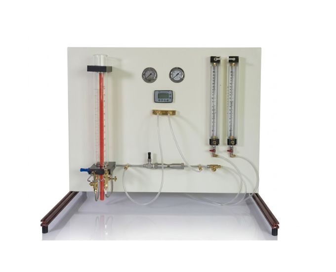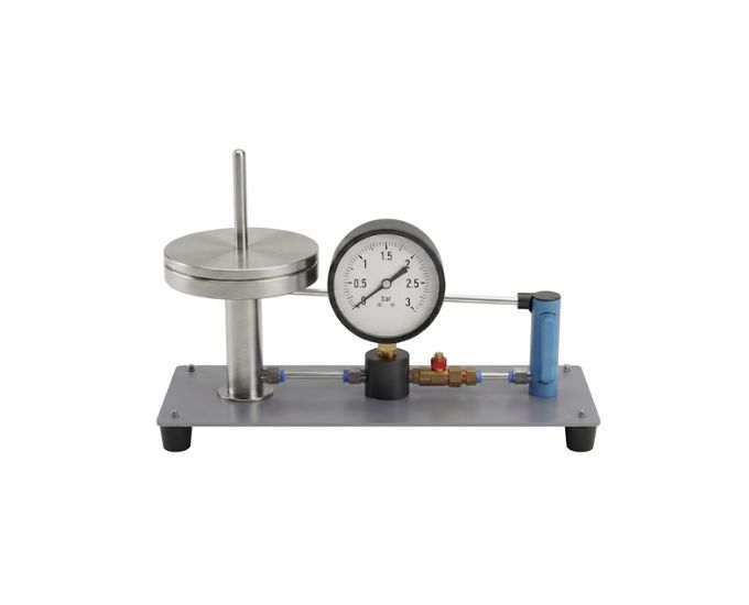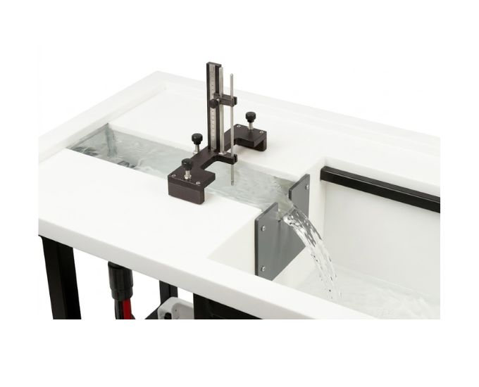

Pipe Network Apparatus
Product Specification Sheet
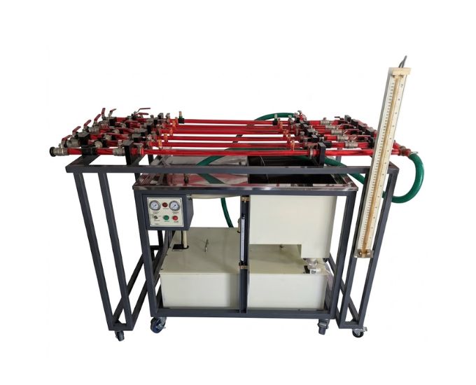
Pipe Network Apparatus
Model Number: MTHB-150.25
The Pipe Network Apparatus is an educational fluid mechanics laboratory system designed for studying pressure losses at various piping elements and within pipe networks. It also enables students to investigate parallel and series connections of pipe sections, measure pressure and flow behaviour, and understand how different network configurations influence head loss, flow distribution, and overall hydraulic performance.
Product Specification
The Pipe Network Apparatus is a comprehensive educational laboratory system developed for the practical investigation of fluid flow through interconnected piping systems.
Manufactured by Micro Technologies, the apparatus provides students with hands-on experience in studying pressure losses at various piping elements and pipe networks, as well as the behaviour of pipe sections connected in series and parallel.
Practical piping installations frequently consist of multiple pipe sections, valves, fittings, branches, and junctions rather than a single straight pipe. Understanding the interaction between these components is therefore essential for the analysis and design of real hydraulic systems.
The apparatus incorporates several pipe sections arranged within an integrated hydraulic network. Appropriate valves enable the flow path to be changed so that different experimental configurations can be established.
Students can configure selected pipe sections in series, where the same flow passes successively through multiple pipe sections. Pressure measurements can then be used to investigate the cumulative head loss produced by the connected sections.
The apparatus also allows pipe sections to be operated in parallel. Under parallel conditions, the total incoming flow divides between different branches before recombining downstream. This enables students to investigate flow distribution and the hydraulic behaviour of parallel branches.
Pressure tapping points are provided at suitable locations throughout the network. These allow pressure differences and head losses across different pipe sections and piping elements to be measured.
By varying the water flow rate and network configuration, students can investigate the influence of pipe resistance, fittings, valves, flow rate, and network arrangement on pressure loss.
Experimental observations can also be used to compare measured network behaviour with theoretical pipe-flow calculations. This provides valuable practical experience in hydraulic network analysis.
The apparatus is particularly suitable for fluid mechanics, hydraulic engineering, civil engineering, mechanical engineering, water resources, and process engineering laboratories.
Features
- Comprehensive pipe network experimental system
- Multiple interconnected pipe sections
- Series connection of pipe sections
- Parallel connection of pipe sections
- Pressure loss measurement
- Head loss investigation
- Multiple pressure tapping points
- Adjustable flow-control valves
- Different hydraulic flow paths
- Branch flow investigation
- Suitable for pressure distribution studies
- Study of losses through piping elements
- Network flow analysis
- Suitable for theoretical and experimental comparison
- Clearly arranged piping system
- Robust laboratory frame
- Suitable for repeated student experiments
Benefits
- Provides practical understanding of pipe networks
- Demonstrates series and parallel pipe connections
- Enables pressure losses to be measured
- Helps students understand flow distribution in branches
- Demonstrates cumulative losses in series pipelines
- Enables comparison of different piping configurations
- Provides practical hydraulic network analysis
- Helps students understand pipe and fitting resistance
- Supports theoretical and experimental comparison
- Provides hands-on pressure and flow measurement experience
- Relevant to real-world water distribution and industrial piping systems
Product Specifications
| Specification | Details |
|---|---|
| Product Name | Pipe Network Apparatus |
| Product Type | Fluid Mechanics Experimental Apparatus |
| Working Medium | Water |
| Experimental System | Multi-Section Pipe Network |
| Primary Study | Pressure Losses in Pipe Networks |
| Pipe Configuration | Series & Parallel |
| Pressure Measurement | Multi-Point Pressure Measurement |
| Pressure Tappings | Provided at Suitable Network Locations |
| Flow Control | Multiple Adjustable Valves |
| Flow Paths | Selectable / Reconfigurable |
| Parameters Studied | Pressure, Head Loss & Flow Distribution |
| Network Analysis | Series and Parallel Pipe Sections |
| Construction | Laboratory-Grade Pipe Network |
| Mounting | Rigid Supporting Frame |
| Operation | Educational / Experimental |
| Application | Fluid Mechanics & Hydraulic Engineering Laboratories |
Main Components
The apparatus typically incorporates:
- Multiple pipe sections
- Series pipe-flow sections
- Parallel pipe-flow branches
- Pipe junctions
- Flow-control valves
- Pressure tapping points
- Pressure measurement arrangement
- Water inlet connection
- Water return or outlet arrangement
- Flow measurement facility
- Supporting laboratory frame
- Hydraulic connecting lines
Experiments Performed
- Study pressure losses at various piping elements
- Determine pressure losses within a pipe network
- Investigate series connection of pipe sections
- Investigate parallel connection of pipe sections
- Measure pressure at different points in a pipe network
- Determine head loss across individual pipe sections
- Determine total head loss in series-connected pipes
- Study flow distribution in parallel branches
- Compare hydraulic behaviour of series and parallel arrangements
- Study the effect of flow rate on pressure loss
- Investigate pressure distribution throughout a piping network
- Study the influence of valves and fittings on network losses
- Compare experimental results with theoretical calculations
- Analyze practical pipe-network behaviour
Parameters Studied
The apparatus can be used to investigate:
- Water flow rate
- Flow velocity
- Inlet pressure
- Outlet pressure
- Differential pressure
- Pressure drop
- Head loss
- Pipe resistance
- Branch flow rate
- Total network flow
- Series flow behaviour
- Parallel flow behaviour
- Hydraulic network characteristics
Series Connection of Pipes
When pipe sections are connected in series, the same flow rate passes successively through each pipe section.
The total head loss across the network can be considered as the sum of the losses through the individual sections:
hL,total = hL1 + hL2 + hL3 + ...
The apparatus allows students to measure these losses experimentally and understand how adding pipe sections and piping elements increases overall hydraulic resistance.
Parallel Connection of Pipes
When pipe sections are connected in parallel, the incoming flow divides among multiple branches.
The total flow rate is related to the individual branch flows:
Qtotal = Q1 + Q2 + Q3 + ...
For branches connected between common upstream and downstream junctions, the head difference across each branch is related to the same junction conditions.
The apparatus allows students to investigate how flow divides according to the hydraulic resistance of individual branches.
Pressure Losses in Pipe Networks
Pressure losses in a practical piping network can result from:
- Pipe-wall friction
- Pipe length
- Pipe diameter
- Flow velocity
- Valves
- Bends
- Junctions
- Flow restrictions
- Changes in flow direction
- Local piping elements
By measuring pressures at multiple points, students can determine how hydraulic energy decreases as water moves through the network.
Educational Objectives
The apparatus helps students understand:
- Pipe network analysis
- Pipes connected in series
- Pipes connected in parallel
- Pressure losses
- Head losses
- Flow distribution
- Pipe resistance
- Branch flow
- Hydraulic energy losses
- Pressure measurement
- Network operating conditions
- Practical piping-system behaviour
Engineering Applications
The principles demonstrated using the apparatus are relevant to:
- Municipal water distribution networks
- Industrial piping systems
- Building water supply systems
- Process plants
- Irrigation networks
- Fire protection piping
- HVAC water circuits
- Cooling-water networks
- Pumping stations
- Water treatment plants
- Chemical processing facilities
- Hydraulic distribution systems
Applications
- Fluid Mechanics Laboratories
- Hydraulic Engineering Laboratories
- Mechanical Engineering Laboratories
- Civil Engineering Laboratories
- Water Resources Engineering Laboratories
- Chemical Engineering Laboratories
- Process Engineering Laboratories
- Environmental Engineering Laboratories
- Engineering Colleges
- Universities
- Polytechnic Institutes
- Technical Training Centres
- Research Laboratories
FAQs
What is a Pipe Network Apparatus?
A Pipe Network Apparatus is an educational fluid mechanics laboratory system used to study pressure losses, flow distribution, and hydraulic behaviour in interconnected piping systems.
What is the main purpose of this apparatus?
The main purpose is to investigate pressure losses at various piping elements and pipe networks and study parallel and series connections of pipe sections.
Can pipes in series be studied?
Yes. The apparatus allows selected pipe sections to be connected in series so that cumulative pressure and head losses can be investigated.
Can parallel pipe connections be investigated?
Yes. Parallel branches can be studied to understand how the total flow divides between different flow paths.
What happens to flow in series-connected pipes?
Under steady incompressible conditions without intermediate branches, the same volumetric flow rate passes through each pipe section connected in series.
What happens to flow in parallel-connected pipes?
The incoming flow divides among the parallel branches, with the distribution depending on the hydraulic resistance of each branch.
Can pressure losses be measured at different points?
Yes. Pressure tapping points allow pressure differences and head losses to be measured at suitable locations throughout the network.
Can the effect of valves and piping elements be investigated?
Yes. Valves and other piping components contribute to hydraulic resistance and can be included when analysing overall network pressure losses.
Can theoretical and experimental results be compared?
Yes. Measured flow rates and pressure losses can be compared with theoretical pipe-network calculations.
Where are pipe-network principles used in practice?
They are widely applied in water distribution, industrial piping, HVAC systems, irrigation, fire protection, process plants, cooling systems, and hydraulic networks.
Is this apparatus suitable for engineering colleges?
Yes. It is suitable for civil, mechanical, hydraulic, chemical, process, environmental, water resources, and fluid mechanics engineering laboratories.
Why Choose Our Products
- Series and parallel pipe experiments
- Comprehensive network-flow analysis
- Multi-point pressure measurement
- Pressure and head-loss studies
- Branch flow investigation
- Multiple configurable flow paths
- Practical hydraulic network training
- Robust laboratory construction
- Suitable for repeated student experiments
- Institutional and bulk laboratory supply
- Customized configurations available
- Technical and project support
Call to Action
Looking for a reliable Pipe Network Apparatus for your fluid mechanics laboratory? Micro Technologies manufactures and supplies pipe-flow, fluid mechanics, and hydraulic engineering laboratory equipment for universities, engineering colleges, polytechnics, research institutes, and technical training centres. Contact us for complete laboratory setups, customized configurations, institutional projects, bulk requirements, distributor inquiries, or a competitive quotation.