
Energy Losses in Piping Elements Apparatus
Product Specification Sheet
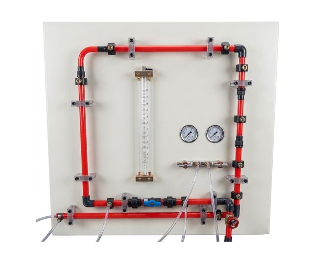
Energy Losses in Piping Elements Apparatus
Model Number: MTHB-150.20
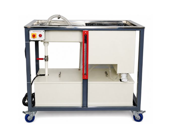
The Energy Losses in Piping Elements Apparatus is an educational fluid mechanics laboratory system designed for studying pressure losses in various pipe fittings and valves. It allows students to investigate local or minor energy losses caused by changes in flow direction, restrictions, fittings, and valves while developing practical knowledge of pressure drop, head loss, and loss coefficients in piping systems.
Product Specification
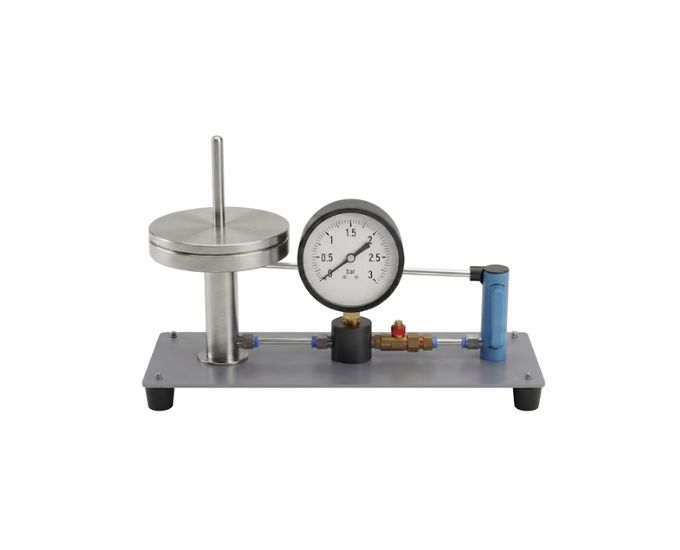
The Energy Losses in Piping Elements Apparatus is a practical laboratory system developed to investigate the energy and pressure losses that occur when water flows through common piping components.
Manufactured by Micro Technologies, the apparatus provides students with hands-on experience in measuring and analysing pressure losses across various pipe fittings and valves.
In an ideal fluid system, mechanical energy would remain unchanged along the flow path. In practical piping systems, however, energy is dissipated due to fluid friction, turbulence, flow separation, changes in direction, and restrictions created by pipeline components.
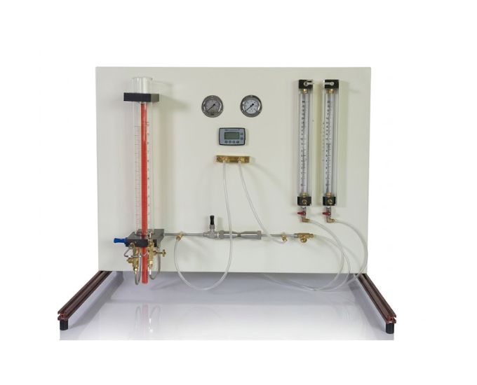
The apparatus incorporates a piping circuit containing different fittings and valves. Pressure tapping points are provided at suitable locations before and after the test elements so that the pressure difference across each component can be measured.
A differential pressure measuring arrangement allows students to determine the pressure drop associated with the selected fitting or valve. By conducting experiments at different water flow rates, the relationship between fluid velocity and local head loss can be investigated.
The system is particularly useful for studying minor or local losses. Although these losses are called minor losses in fluid mechanics terminology, they can become significant in practical piping systems containing multiple bends, valves, fittings, and flow restrictions.
Experimental measurements can be used to determine the loss coefficient (K) for suitable piping elements. Students can then compare experimentally determined values with theoretical or reference values.
The apparatus provides practical understanding of how piping components influence total system resistance and why energy losses must be considered when selecting pumps and designing hydraulic networks.
Its clearly visible piping circuit, measuring instruments, control valves, and compact panel arrangement make the apparatus suitable for engineering laboratory practicals and demonstrations.
Features
- Study of energy losses in piping elements
- Pressure loss measurement across pipe fittings
- Pressure loss measurement across valves
- Multiple piping components
- Clearly arranged experimental pipeline
- Pressure tapping points
- Differential pressure measurement
- Adjustable water flow rate
- Flow-control arrangement
- Head-loss determination
- Minor loss investigation
- Loss coefficient determination
- Suitable for comparative experiments
- Clearly visible hydraulic circuit
- Compact laboratory configuration
- Robust supporting panel
- Suitable for repeated student experiments
Benefits
- Provides practical understanding of piping energy losses
- Demonstrates pressure drop across fittings and valves
- Helps students understand minor or local losses
- Enables different piping elements to be compared
- Allows loss coefficients to be determined experimentally
- Demonstrates the effect of flow velocity on head loss
- Provides practical pressure measurement experience
- Supports theoretical and experimental comparison
- Helps students understand piping-system resistance
- Provides useful knowledge for practical pipeline design
Product Specifications
| Specification | Details |
|---|---|
| Product Name | Energy Losses in Piping Elements Apparatus |
| Product Type | Fluid Mechanics Experimental Apparatus |
| Working Medium | Water |
| Primary Study | Energy & Pressure Losses |
| Test Elements | Various Pipe Fittings & Valves |
| Pressure Measurement | Differential Pressure Arrangement |
| Pressure Tappings | Provided Across Test Elements |
| Flow Control | Adjustable |
| Parameters Studied | Pressure Drop, Head Loss & Loss Coefficient |
| Loss Type | Local / Minor Losses |
| Hydraulic Circuit | Integrated Piping Arrangement |
| Measurement Conditions | Variable Flow Rates |
| Mounting | Laboratory Panel / Supporting Frame |
| Operation | Educational / Experimental |
| Application | Fluid Mechanics & Hydraulic Engineering Laboratories |
Piping Elements Studied
Depending on the supplied laboratory configuration, the apparatus can be used to investigate losses associated with common piping elements such as:
- Pipe bends
- Elbows
- Valves
- Changes in flow direction
- Local restrictions
- Pipe fittings
- Flow-control elements
- Other suitable hydraulic components
Experiments Performed
- Measure pressure losses in various pipe fittings and valves
- Determine head loss across piping elements
- Study local energy losses in a pipeline
- Investigate minor losses in pipe flow
- Measure differential pressure across selected components
- Study the effect of flow rate on pressure loss
- Study the effect of fluid velocity on head loss
- Compare losses across different pipe fittings
- Compare pressure losses across different valves
- Determine loss coefficients for suitable piping elements
- Study energy dissipation in piping systems
- Compare experimental and theoretical loss characteristics
- Investigate the contribution of fittings to total pipeline resistance
Parameters Studied
The apparatus can be used to investigate:
- Water flow rate
- Flow velocity
- Inlet pressure
- Outlet pressure
- Differential pressure
- Pressure drop
- Head loss
- Local energy loss
- Minor loss
- Loss coefficient
- Hydraulic resistance
Energy Loss in Piping Elements
When water passes through a fitting or valve, the flow pattern can change due to alterations in direction, cross-sectional geometry, or local restriction. These disturbances produce turbulence and energy dissipation.
The local head loss is commonly represented by:
hL = K × V² / 2g
Where:
- hL = Local head loss
- K = Loss coefficient
- V = Mean flow velocity
- g = Acceleration due to gravity
Experimental pressure measurements can be used to evaluate the loss associated with a selected piping component.
Pressure Loss Through Fittings
Pipe fittings can alter the direction or distribution of fluid velocity. This may produce:
- Flow separation
- Secondary flow
- Turbulence
- Local pressure reduction
- Energy dissipation
The apparatus allows students to measure these losses and understand their importance in practical pipe networks.
Pressure Loss Through Valves
Valves regulate or isolate fluid flow but also introduce hydraulic resistance. The resulting pressure loss depends on factors such as:
- Valve geometry
- Flow rate
- Fluid velocity
- Flow restriction
- Operating position
The apparatus enables students to investigate valve-related pressure losses under controlled laboratory conditions.
Educational Objectives
The apparatus helps students understand:
- Energy losses in pipe flow
- Pressure drop
- Head loss
- Minor or local losses
- Pipe fitting losses
- Valve losses
- Loss coefficients
- Differential pressure
- Effect of flow velocity
- Hydraulic resistance
- Energy dissipation
- Practical pipeline analysis
Engineering Applications
The principles demonstrated by the apparatus are relevant to:
- Water distribution networks
- Industrial piping systems
- Pumping installations
- Process plants
- HVAC systems
- Cooling-water circuits
- Water treatment plants
- Chemical processing systems
- Irrigation networks
- Building services
- Hydraulic systems
- Pipeline design
Applications
- Fluid Mechanics Laboratories
- Hydraulic Engineering Laboratories
- Mechanical Engineering Laboratories
- Civil Engineering Laboratories
- Chemical Engineering Laboratories
- Process Engineering Laboratories
- Water Resources Engineering Laboratories
- Engineering Colleges
- Universities
- Polytechnic Institutes
- Technical Training Centres
- Research Laboratories
FAQs
What is an Energy Losses in Piping Elements Apparatus?
It is a fluid mechanics laboratory apparatus designed to measure and investigate energy and pressure losses produced when water flows through different pipe fittings and valves.
What is the main objective of this apparatus?
The main objective is to study pressure losses in various pipe fittings and valves and understand their effect on piping-system performance.
What are minor losses in pipe flow?
Minor losses are localized energy losses associated with components such as bends, valves, fittings, contractions, expansions, and other disturbances in a pipeline.
Can pressure loss across individual fittings be measured?
Yes. Pressure tapping points allow the pressure difference across selected piping elements to be measured.
Can valve losses be investigated?
Yes. The apparatus is designed to investigate pressure and energy losses associated with suitable valves included in the experimental circuit.
What is a loss coefficient?
The loss coefficient, commonly represented by K, is a dimensionless parameter used to characterize the local head loss produced by a particular piping component.
Does flow velocity affect energy loss?
Yes. Local head losses are strongly related to fluid velocity and generally increase significantly as velocity increases.
Can different fittings be compared?
Yes. Experimental measurements allow students to compare the hydraulic resistance and pressure losses associated with different piping elements.
Why are piping losses important in engineering?
Accurate knowledge of piping losses is important for determining pump requirements, predicting system pressure, selecting pipe components, and designing efficient fluid transport systems.
Is this apparatus suitable for engineering colleges?
Yes. It is suitable for mechanical, civil, hydraulic, chemical, process, water resources, and fluid mechanics engineering laboratories.
Why Choose Our Products
- Multiple piping-loss experiments
- Pressure loss measurement across fittings and valves
- Minor head-loss investigation
- Loss coefficient determination
- Variable flow-rate studies
- Practical pressure measurement
- Clearly arranged hydraulic circuit
- Robust laboratory construction
- Suitable for repeated student experiments
- Institutional and bulk laboratory supply
- Customized configurations available
- Technical and project support
Call to Action
Looking for a reliable Energy Losses in Piping Elements Apparatus for your fluid mechanics laboratory? Micro Technologies manufactures and supplies fluid mechanics, pipe-flow, and hydraulic engineering laboratory equipment for universities, engineering colleges, polytechnics, research institutes, and technical training centres. Contact us for complete laboratory setups, customized configurations, institutional projects, bulk requirements, distributor inquiries, or a competitive quotation.